This project was one of my first BIG projects! The 5x5x5 LED Matrix is a cube made of LEDs (stands for Light Emitting Diode which are essentially mini lights) that light up in various patterns for the viewer enjoyment!
This project took me roughly 2 months to make, and while it was a long process, I loved every minute of it! I learned so much about circuits (including the seemingly never-ending troubleshooting phase). Here’s what the process looked like…
Step 1: Suffer Through Sanding
LEDs happen to be quite bright. And reflective. This means that if you were to put a lit up LED near one that isn’t, the light would reflect of it, making the one that isn’t lit, appear to lit up!
How did this affect the project process? Well, in order to prevent the light of a lit up LED from making the “turned off” LEDs look lit up, I had to dull down the LEDs first. By sanding them. By hand. One by one.
Remember how I said it was 5x5x5 Matrix? That means I had to sand 125 LEDs by hand before even starting the project! It was quite tedious, but looking back, it’s almost funny!
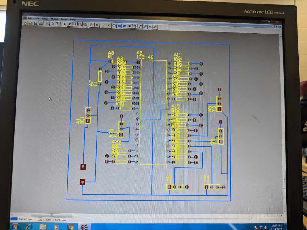
Step 2: Designing the Circuit Board
Using Traxmaker, I designed the circuit board for this project based off the paper schematic. There was a lot more components in this project, so it did take a while to fit everything in. Overall though, not that bad!
Step 3: Bringing the Circuit Board to Life!
After printing the schematic and etching the copper board with the circuit design, it was time to add the components onto the board, bringing it to life! This included drilling holes into the board for the components, soldering the components in, and (attempting to) trim it up to look neat:
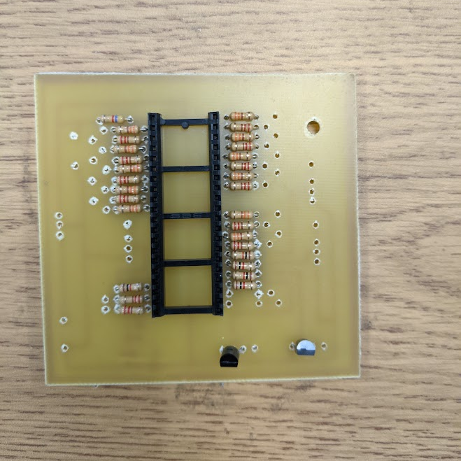

Looking back, the soldering is definitely messy…but cheers to progress!
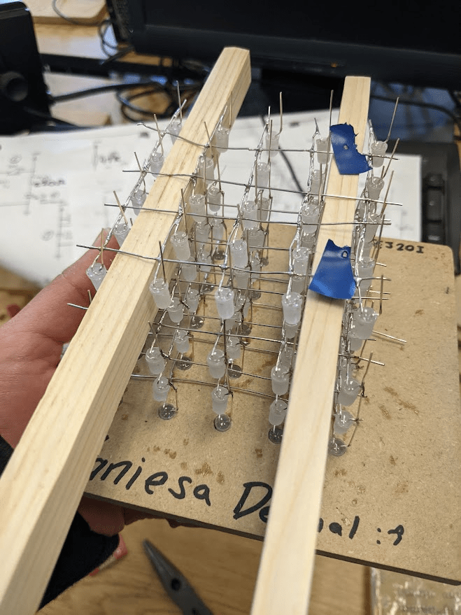
Step 4: Constructing the Base!
Remember the 125 LEDs that I sanded? Well, it’s time to put them to use! Using some blocks of wood from my school woodshop, I got a base ready for the project, and starting soldering the LEDs together in a cube shape.
Being honest here, it was really hard. I had to use the same rectangular piece of wood to place the LEDs on as I soldered them to the LEDs below and next to it. In order to reach my perfectionist standards, I tried my best to make sure the layers and spacing was equally spaced. I had re-start and re-solder many LEDs, especially since I wanted the solder connections to be as neat and thin (but still stable) as possible!
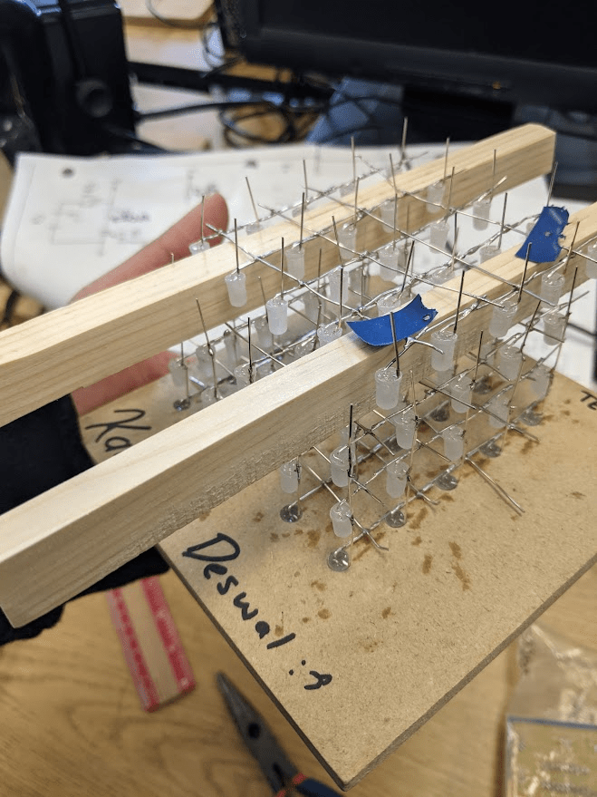
Did I forget to mention I had to do this upside down? The most efficient way to do this was to go top-layer down!
Step 5: Coding!
Finally, I had to code the LED matrix! I had to use a specific and unique code for this, rather than a main-stream coding language. However, I had a trusty coding booklet to get me through the process.
This step surprisingly required the most creativity. I had to find unique LED display patterns, even with certain restrictions of the code and hardware. For example, I couldn’t light up individual LEDs only a row or column of LEDs. (I would need a lot more wires if I wanted each LED to be able to light up seperately…)
At one point, I had trouble visualising the patterns I wanted to display, so I went on an frame-by-frame animation game to draw out how each row or column of LEDs would light up to create my display patterns!
My personal favourites are the last two: the windmill and the diagonal pattern! I had to use a special trick for them, which was taking advantage of the fact that our eyes can only process lights at a certain speed (meaning there were far more lights being lit up than you actually saw!)
So which pattern is your favourite?

Leave a comment