Lab #5: The Clock
This lab sent continuous pulses to an LED, in such a way that it flashed once every second, like a clock! The way it works is actually the exact same as my LED Chaser Project (aka the light up Kitty). However, now that I better know how gates work, it seems so much cooler. Similar to my previous post on the breadboard labs, here’s a schematic with an explanation followed by the final result:
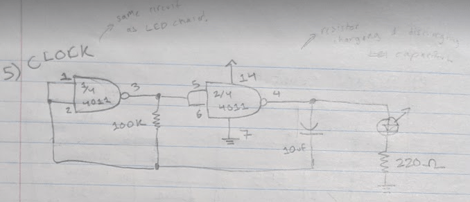
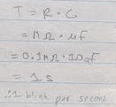
The leftmost image shows the circuit. How it works is that the 100K resistor charges and discharges the capacitor through passing the NAND gates, causing the pulses. The speed of the pulses is calculated by the resistance (in mega-ohms, MΩ) multiplied by the capacitor value (see image on right).
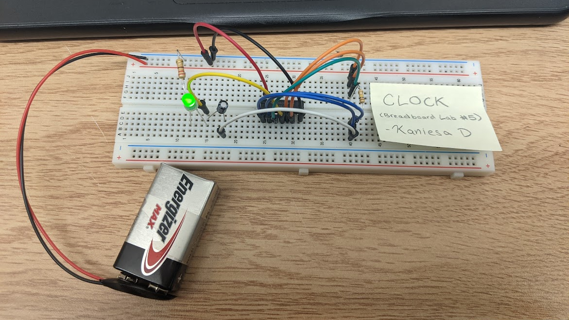
Picture & Video:
Lab #6: The Timer
In the Timer Breadboard Lab, an LED would light up for a set amount of time after pushing a button. Now, in the lab, I had used a wire instead of a button, but (by connecting and disconnecting the wire) it works all the same! Here’s the circuit schematic:

Now, I remember having to ask for an extra explanation because I had trouble understanding this one, so forgive me if this explanation isn’t the best. But basically, when the button is pressed the LED turns on and the capacitor begins to charge. When the button is released, the LED delays in turning off due to it still lighting up from the charge of the capacitor. Once the capacitor is discharged once more, the LED shuts back off.
Picture & Video:

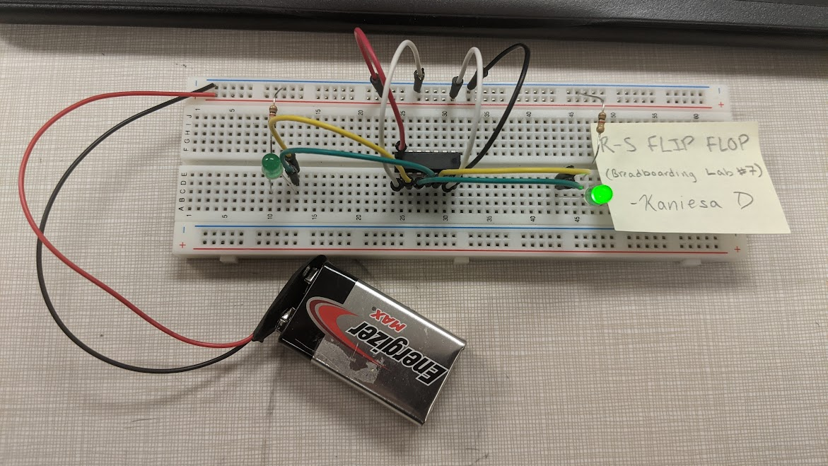
Lab #7: The R-S Flip Flop
Now, this last Breadboard Lab (of this post), is a little bit different from the previous ones. The R-S Flip Flop, which is short for the Reset-Set Flip Flop circuit, works by lighting up an LED and only switching which LED is lit up when the power and ground wires are manually switched. Here’s the circuit schematic:
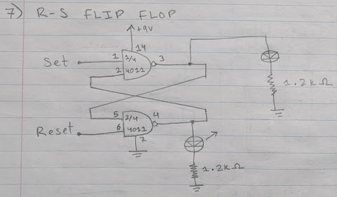
There are two inputs for this, each one connecting to a NAND Gate. If one input is negative, let’s say it’s SET, then output of the NAND Gate will be 1 no matter what. This means that LED connected to the output will turn on. Furthermore, this also means the input going into the NAND in front of the RESET will be 1. Combined with the 1 from the RESET (as we’re under the assumption that the inputs are opposite), the output becomes 0, meaning the other LED stays off. If you switch the positive and negative, then vice versa- the LED that was off is on and the other on turns on. Cool how it works, isn’t it? I love how the inputs are all connected in this fun flip flop way : )
Last, but not least, here is the picture and video for this Breadboard Lab:
Post-Labs Reflection
Once again, I had a great time making these circuits! Just like I mentioned in my previous post, I had finished very quickly again- one day after I finish the first four labs, I had quickly worked my way through these labs. Not that I was rushing, but it just goes to show how quickly time passes and things get done when your having fun.
I can’t wait to add the last installation of this breadboard labs post series!
Be back soon,
– K.D

Leave a comment