There it is. Today I finally finished my Line Following Robot. It took far longer than expected, but it’s finally done! The joy I felt watching the little guy roll along the track made my heart burst with joy.
…
Maybe I should explain what exactly I’m talking about. As a part of my grade 11 Computer Engineering/Technology course, I made a robot that can, as the title suggests, move and follow along a line. Specifically a black (or dark) coloured line. This is because it can differentiate between light and dark colours.
Here’s how it works in simple terms:
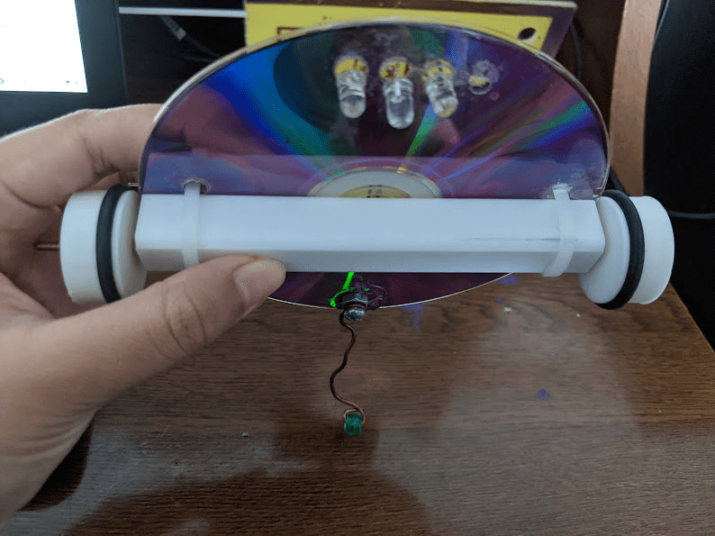
- An LED attached to the bottom of the bot shines a light on the floor
- Fun Fact: black surfaces don’t reflect light. white surfaces reflect light.
- If the LED shines on a white surface, light is reflected back up, specifically into one of the two phototransistors that are also attached to the bottom of the robot
- The phototransistor, detect light, so if there’s a high enough amount of light detected, then the robot knows it’s on a white surface (because light was reflected)
- Similarly, if no light reflects into a phototransistor, it knows it’s on a black/dark surface.
- Since the robot follows a black line, it shuts off the motors when it’s on a white surface.
- The robot can shut off one motor if it needs to turn. It can turn because the two phototransistors are placed to the right and left of the bot, telling it which direction the light is reflecting from.
Okay! I know that was a lot to read, but I hope it makes sense? I left out some of the more specific details on how each component plays a role, but it’s really cool how everything ties together. Also, so many resistors were used. I always knew resistors were important in circuits (literally stops you from frying everything) BUT they do so much more than that! For example, I had no idea what a pull-up resistor even was until doing the project!
Sneak Peek Into The Building Process
The Disk
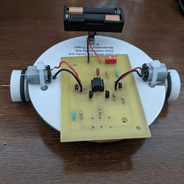
As you may have seen from the image above, the robot in fact, was built on a disk. Why? Because it’s cheap and light-weighted. The cheap part is especially important because let me tell you, drilling holes into a disk is very troublesome. If you don’t do a good job, you can very easily crack and break the disk. I would know. It took me three disks. I’m not very proud of it, but I doubt there will be many projects in future that involve me drilling holes into disks. Or maybe I just jinxed myself by saying that. Who knows.
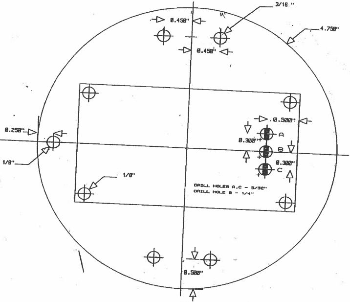
If you look at the image above, every one of those circles in the disk is a hole I had to drill, except for two of the corner ones in the “rectangle,” which represents the circuit board. This is because I really only needed to drill the corners to attach and secure the circuit board. The three other holes in the circuit board area (with the black rectangles in them) were for the LED and phototransistors. The sets of two holes on the side for the motors, and the one at the back for securing the battery & balance-roller (prevents bot from tipping backwards)
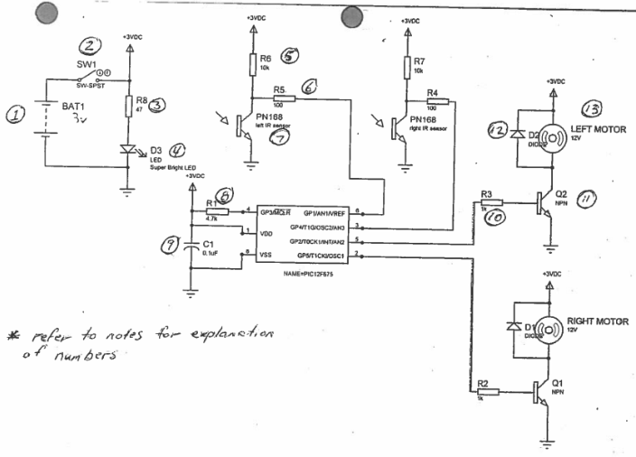
The Schematic
This was another project where I had to take a schematic, design the circuit board for it (on Traxmaker), before etching it and drilling (more) holes into the board for attaching components. The process went relatively well and simple! (much better than the disk-phase)
The Building & Troubleshooting
The hardest part of the project was no doubt arranging the placement of the phototransistors. You see, the processing chip could only handle certain voltage values: below 0.8 is white surface, above 1.8 is black surface, BUT between 0.8 and 1.8 would be a float value ☠️
There was a long process of hooking my bot up to voltmeter, checking the voltage values, seeing it completely out of range, shifting the phototransistors so it’s back in range, only for them to shift too much and be out of range once more.
At one point, I was told that I put too much spacing between the holes in my disk, so the phototransistors would never be close enough to reach my values. This meant I had to go back to disk-phase too. *sigh*
The Result & Reflection
While the video doesn’t have audio, I was most definitely talking and celebrating in the background. I’m so happy with this project, and I can’t wait to use it on the next project I’ve already started: A Sumo Bot! (stay on the lookout for that coming out)
Looking back, there were a lot of parts in this project that I kept failing at. It took me almost 2 weeks longer than what was expected to finish this process. I spent so many lunch breaks working in the computer engineering workshop trying to get it to work. And in the end, it did work. That’s all that matters.
The fact that I persevered, and it paid off, which is one of the reasons I’m interested in pursuing Computer Engineering further. The satisfaction of finally getting a physical, tangible invention made by my own hands to work is more gratifying than almost anything I can think of. It’s a place where you’re constantly puzzling over a problem, and there’s never a day where I don’t learn something new! (even if all what I learn ends up being how much patience you need for drilling disks ;))
Until the next project,
See you soon.

Leave a comment